Raspberry Pi - do try this at home
My 7-year old son has recently started learning about electricity in primary school. As I’ve always tried to get him interested in computing and coding (he’s been using Scratch in a web browser for making drawings for a while), I thought this might be a great opportunity to introduce him to simple circuits and that there’s a hardware layer underneath all these shiny user interfaces. At the same time, I have always been on the lookout for a legitimate reason to buy a Raspberry Pi and reconnect to my old self as a teenage hardware tinkerer.
So here’s the plan: On our explorative journey with the RPi, I’m going to keep a log here for everyone to learn, as seems customary amongst RPi owners. My son would like to build a robot and control it with the RPi (little does he know about the complexity!), for now I’m happy if we can connect it to a breadboard and switch an LED on and off.
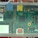
Buying the RPi. I had a look at the project website and half expected to see an “order here” button, assuming that a small charitable enterprise would simply deal with these things. Unfortunately, one has to source the RPi through a third-party dealer, and there is little guidance as to the pros and cons for each of them. A quick Google search confirmed that RS was a known company and I found their website a little easier to navigate than Farnell/Element14. So on RS there is a single page where one can order the appropriate RPi (there are two models A and B), power supply, boot disk and cabling. That was pretty tempting, as I didn’t know much at the time and for £55 ordered and RPi Model B, a case, 4GB SD with RPi OS, a USB power supply and an ethernet cable. Unfortunately, RS was pretty vague on the delivery date and they responded to an enquiry (that I sent 10 days after ordering) with a generic apology. There is a lot of gossip on the internet about RS’s slow handling and I even read of “unwillingness to deliver”. Anyway, after only 14 days the package finally arrived, very much what they had indicated in the order confirmation. However, in the meantime I had lost my patience and had a look around for alternative sources for the RPi. I found that Maplin offers a quite expensive RPi Starter Kit including a USB hub, keyboard and mouse (all of which I didn’t need), for immediate pickup in store. I also found that when looking at the Farnell/Element14 site as a consumer, there is no indication of their stock and availability; however, if you simply go to the business customer pages or Farnell/CPC, you get to see a delivery time estimate. In my case, it said 24 hours, and that’s what’s made me order an RPi Model B, a case and 4GBP SD for £48. Thankfully, it’s not difficult to sell a spare RPi if you know a few geeks. ! :-)
The RPi in headless model. I don’t have the space to dedicate a screen and peripherals to the RPi. I informed myself on the internet and found the gettingstartedwithraspberrypi blog, which explains how to set up a VNC server on it. Note that this was approximately 3 minutes after I first booted my RPi, connected it to my router, and SSH’ed in as pi@…, so it’s really dead-simple. On my iMac, I just pressed Cmd+K, put in the IP address and port (in my case then: vnc://192.168.0.9:5901), and I could use the RPi as additional computer in the house.
A word about power. Part of my RS order was a power supply. The RPi Model B requires 5V and at least 700mA. My phone charger unfortunately wasn’t strong enough (it says 500mA), but I found the marriage of an iPad 5.1V / 2.1A power supply to a Kindle charger cable a workable solution.
Update 7th April 2013.
Wireless. The RPi was the only computer in the house that required a wired connection to my router. Given that I bought it primarily to interact with electronics, I was soon convinced that a wireless adapter was needed. After a wee bit of Google I was convinced that the Maplin N150 Nano USB Wireless Adapter for £10 was the way to go, as it is also included in their Pi starter kit. For the installation of the adapter, I inserted it into the USB socket, booted the system, VNC’ed into it over the wired connection, and used the Wireless GUI icon on the desktop. This immediately recognised the adapter, a press on ‘scan’ found my favourite network, and offered me a form to customise my connection. I saved the option and ready it was. I then removed the ethernet cable, booted the system, and I was ready to fly. Before you close the Wireless GUI, take a note of the IP address your router assigned to it — saves you the pain of guessing.
Breadboard. To get me started with hardware experiments, I had previously bought a Raspberry Pi Cobbler GPIO Super Starter Kit from 4tronix.co.uk for £22. It features a large breadboard, the Adafruit cobbler that connects the RPi to the breadboard (including labelled pins on the board), and a bunch of LEDs, push buttons and about 60 cables. For my first RPi experiments, I followed http://rpi.tnet.com/project/hardware/project001, at least for red “power on” LED and the button. I connected the green LED to a different pin so I have control over it.
Controlling the GPIO. For quick and dirty experiments I installed webiopi from their Google code site. After a first successful play, I immediately hooked it into my startup defaults via sudo update-rc.d webiopi defaults. This now allows to remotely http into the RPi on port :8000, using defaults (webiopi/raspberry) for login. The header view allows direct control of the GPIO pins.
For my own experiments I’m currently trying to use Perl via the Device::BCM2835 module. I was surprised that the standard “sudo perl -MCPAN -e shell” works smoothly on the RPi. The installation of the module was hindered by my inability to read the documentation thoroughly, and only after my third failed attempt I realised I had to install a C library from the authors home page. The installation worked exactly as described on his bcm2835 site.
Update 20th April 2013.
Scratch and GPIO interaction. I haven’t updated this in a while, primarily because I’ve started building more complex circuits on the breadboard (without the RPi) to get the hang of it before I embark on something ‘serious’. As said before, I’m doing this mostly to entertain my two boys, and I found my Perl code that deals with the GPIO through the BCM2835 chip pretty unintuitive. Also, Perl is probably not a good scripting language to start with anyway, so I looked into using the GPIO through Scratch.

It seems the way to go is a Python script that listens to Scratch, so that the youngsters are protected from too many confusing technical details. At http://cymplecy.wordpress.com/2012/08/26/scratch-controlling-the-gpio-on-a-raspberrypi I found a pretty quick explanation and the necessary script to make this work. One does a quick wget to retrieve the source files from the author, followed by a shell script that comes from him. This leaves a new item on your Desktop called ScratchGPIO, which is effectively the same Scratch but with the Python script running in the background.
What’s slightly annoying is the fact that they use the pin number, and not the labels printed on the Adafruit Cobbler that I’m using. However, that aside, individual pins can easily queried using the Sensing submenu in Scratch, and you can directly set pin11 on, for example (it’s all explained in the above link). I was trying to query the pins directly, but it’s apparently not meant to be. Thanks to the Penguin Tutor’s 7-year old daughter for a useful code snippet that allowed me to learn.
The colourful code in the picture is a simple painting script that moves and turns the graphical cursor following pushes on the physical buttons on the breadboard.
Update 7th May 2013.
Listening to the outside world with the Raspberry Pi. In the meantime I’ve become more serious about hardware. If you really want to do “sensoring”, you don’t get around choosing an analog-digital-converter (ADC) for your experiments. For a mere £12, I had gotten myself an MCP3008 10bit ADC, a TMP36 temperature sensor and a light-dependent resistor along with assorted bits and pieces (to make use of my £3 shipping! from skpang.co.uk). As so often, Adafruit came to rescue with a splendid explanation as to how to wire it all up and how to use Python to query the ADC. The entire manual can be found here: http://learn.adafruit.com/reading-a-analog-in-and-controlling-audio-volume-with-the-raspberry-pi/overview.
The next update will likely contain information on the Ciseco XRF wireless modules that allow remote sensoring, but that was hindered over the weekend due to some bad soldering on my behalf…