How to make a battery last forever...
Many devices in the IoT won’t be mains powered, but require some sort of supply with limited capacity: be it common batteries or rechargeable cells, energy management is a key challenge for the development of IoT products.
Background
The basic anatomy of a program on a microcontroller (the little green boards that run the logic of many digital devices) is an infinite loop: as long as you’re powered, do…
Unfortunately, even “doing nothing” costs energy. While a processor is powered, it’s always going to draw some current for the most basic housekeeping. And it’s not just the processor: voltage regulators, interfaces, nearly everything that is connected to a circuit eats up electricity, and most of it is lost in the form of heat.
The data in this section primarily comes from a very good blog post on Power saving techniques for microprocessors by Nick Gammon. Let’s look at an example: Just running an empty loop on the Ardunio Uno (a commonly used microcontroller for hobbyists) draws about 50 mA. That is, with a standard 9V block (supplying 500 mAh), that Arduino can run just about 10 hours from a battery. Clearly not long enough for a hardware product that’s aimed to participate in the IoT.
Processor manufacturers are well aware of this issue and most platforms support a sleep mode. In case of the Arduino Uno, adding just four lines of code reduces the cost of the empty loop to 35 mA. This is still significant, but mostly owed to all the other components on the microcontroller (including a cheerfully blinking light and a wasteful voltage regulator that takes the 9V of the battery and supplies 5V to the board).
Fortunately, ‘real products’ don’t require all the baggage that the Arduino Uno is carrying around. The processor, the Atmel Atmega328, really just draws 0.35 mA in its most optimal sleep mode. If we don’t require particular features of the processor, this can further be reduced to less than 0.5 uA. (Note that this would allow a 500 mAh battery to drive the processor for 10 years – unfortunately, doing absolutely nothing!).
“But IoT devices are supposed to do things!”, I hear you say. Even more so, the hardware to send information into the Internet can be quite energy hungry – remember the times when it was recommended to switch Wifi off while you were on the road with your laptop? Now, many IoT devices, sensors in particular, only need to work in bursts.
Let’s take a look at one of our favourite core components in connected products: The RFu328 from Wireless Things. It combines a barebones Atmega328 with a transceiver that can send and receive radio messages to and from an Internet-connected hub device. The processor and the radio can be sent into a deep sleep, drawing 0.5 uA. However, there’s a timer inside the radio that can trigger the Atmega328 chip and wake the entire system, ready to send or receive data at about 30 mA. We may even have to supply electric current to external sensor hardware and increase our need to more than 50 mA for a second, but for our overall energy budget that’s rather marginal – most of the time, our device will be asleep for minutes if not hours.
Implementation
For the standard Atmega sleep modes, consult Power saving techniques for microprocessors.
The sleep modes of the RFu328 depend on a simple modification to the hardware as well as a library from Wireless Things. In the absence of in-depth documentation, we learned a lot from PCB designs and software examples from the Oxford Flood Network.
In short, the RFu328 can configure the radio to go into the extended sleep mode by sending the ATSM3 AT command. The Wireless Things library handles a lot of the high-level “+++” string handling to communicate with the SRF radio.
Most of the setup magic happens here:
uint8_t setupSRF(char* sleepString) { // set Sleep mode 2
   if (!enterCommandMode()) { // if failed once then try again
     if (!enterCommandMode()) return 1;
     if (!sendCommand(sleepString)) return 2;
     if (!sendCommand("ATSM3")) return 3;
     if (!sendCommand("ATDN")) return 4;
   return 5;
   }
and sleepString is a combination of a configuration suffix and the millisecond sleep duration in hexadecimal notation: ATSD1388 – 5 sec; ATSD4E20 – 20 sec; ATSDEA60 – 1 min; ATSD493E0 – 5 min; ATSD1B7740 – 30 min; ATSD36EE80 – 60 min
Everytime the radio wakes up from this sleep, it triggers a pin of the Atmega328, and having
LLAP.sleep(WAKE_PIN, RISING, false); // sleep until woken
as part of your loop() takes care of listening to that signal.
Hardware
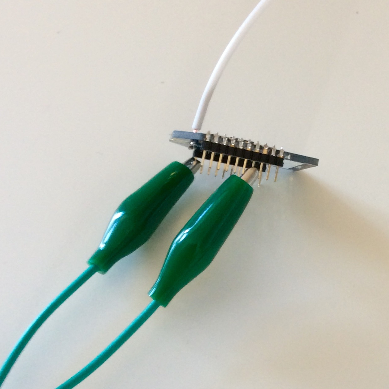
So how does the WAKE_PIN (either D2 or D3) get its signal from the SRF? Via a bridge from D11. (A simple wire.) If you have a newer model of the RFu328, there’s a small field labelled ATSM3. This allows you to create a direct solder bridge to D2 or D3 without the need for the wire.
What other hardware modifications may be necessary? Well, most sensors have a quiescent current draw even when they’re not active. Would it not be nice to have them seperated from the battery until they’re really required? That’s exactly what we’re going to do. Transistors can be used to interrupt the flow of current until triggered, and the RFu328 has a sufficient number of pins remaining that allow for controlling (gating) as MOSFET.
An OpenSensors example on GitHub.