Quality checks for small batch production
Today I want to reflect a bit on quality checks (QC) in small batch production runs. That is, how do you check your electronics hardware when you’re past the prototyping stage but you haven’t quite arrived at automated manufacturing and testing.
I hesitated to post this as I can’t really come up with general rules and I’m sure many people have already perfected this step. However, Twitter encouraged me to report my limited experience with the passive-infrared motion sensors I deployed recently for a customer.
.@BorisAdryan What audiences might appreciate is your view, "Where will this take us tomorrow?" Opportunities, risks, considerations.
— PeterCorless (@PeterCorless) October 15, 2015
Also, that stuff needs to be documented, so I might as well do it in public.
Anatomy of the device
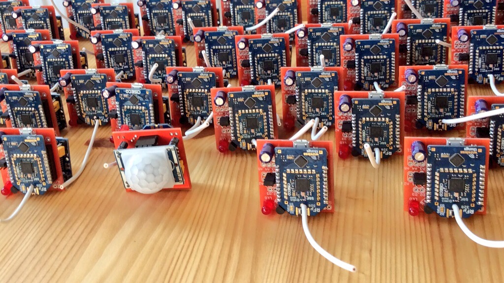 The picture shows the device from two sides. One side carries an off-the-shelf HC-SR501 passive-infrared motion sensor (PIR; the white dome) that reacts to movement of warm-blooded animals. The other side features a Wirelessthings RFμ328 Arduino-compatible microcontroller with on-board radio capability to relay the state of the PIR.
Here’s a close-up together with an AA battery for size comparison:
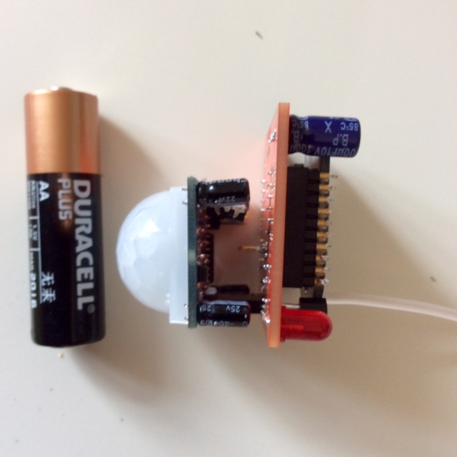
For the purposes of my customer, the device is powered through a micro-USB power adapter at a standard 5V. There’s very little in terms of user interaction, just a LED for status blinks and a jumper for tests. A nice feature is a 1-wire DS18B20 temperature sensor. While the customer didn’t need the temperature reporting, but the 1-wire protocol provides an unique identifier thus that all devices can run with the same hard- and software, but have a distinct identity. Underneath the radio, there is a Wirelessthings PowerPOD (1117) for voltage conversion to 3V3 for the radio module. The 3V3 circuit is further buffered with a 100 μF capacitor. There’s also a 4k7 resistor to enable the use of the DS18B20 in parasite mode.
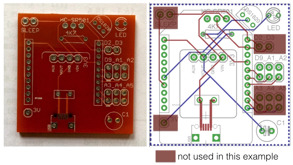 The PCB and the EAGLE board layout.
Perceived gotchas…
From the prototyping stage I was sure to have a functioning board and working RFμ328 code. That is, for one device I was very certain that I’ve designed and built the right thing. But how go about making several dozen? What could fail?
- The USB receptacle is a small SMD component. If the two outermost pins of the receptacle don’t make contact with the landing zone, the board won’t have power.
- I’ve never had issues with the PowerPOD, but are they all going to be fine when I buy a bucket full of them? Same goes for the PIR, the RFμ328, the DS18B20 and even the LED…
- Every single PCB costs money, so how am I going to deal with those potentially failed components?
You don’t want to end up in a situation where you realise that half of your carefully built sensors don’t work, and you have no idea why!
Build strategy
I went over the boards in several iterations.
- In the first iteration, I soldered on the micro-USB receptacles. Once I had finished a batch of ten or so boards, I connected them to a power adapter and tested with a volt meter on points GND and Vin whether I could see 5+V. In some cases I had to go back and refine the solder on the GND/VDD pins.
- In a previous step, I had put all PowerPODs on break-away-header legs.
Large @wirelessthings PowerPOD array. Didn't produce a single Watt after an entire afternoon facing south. pic.twitter.com/GxqVguIEmi
— Boris Adryan (@BorisAdryan) September 12, 2015- The “PowerPODs on stilts” were mounted next. In order to spot any broken voltage regulators (of which there were none), I connected all boards to power and checked for 3V3 with a volt meter on the GND and Vout. Note that I left the overhead of the “stilts” sticking out of the back of the board, allowing me to conveniently touch them with my probes. They’re visible in between the PCB and the PIR in the picture with the battery.
- Next, I put on the 4k7 resistors. (No test).
- In a previous step, I had already attached the header pins to the RFμ328s.
The top shows what Miles does. The bottom shows what Stacey does. Lately, both haven't been happy with each other. pic.twitter.com/zhvgktbuPA
— Boris Adryan (@BorisAdryan) September 25, 2015I inserted the legs into female headers (2mm pitch) and soldered the carefully aligned headers onto the board.
- I then removed all RFμ328 again from the PCB, attached the board to power, and checked whether I could see 3V3 by inserting probes into the 3V and GND positions of the RFμ328 headers. This way I could at least be sure that the radios had power if they would remain silent.
- In the next step I added all passive components (LED, capacitor) and jumper headers. (No test).
- The three pins of the PIR connect to the board through break-away female headers. Here was the most critical test of the board, ensuring that most of the “wiring” of the board was actually functional: I connected the D2 and D12 pins of the radio header with a jumper wire. That is, a voltage coming from the middle PIR pin should be relayed to the positive pole of the LED. After powering the board through micro-USB, this allowed me to test if the PIR was detecting activity, and if so, if the LED could be activated.
- Since the test of the DS18B20 required 1-wire communication, I added this component last before reinserting the RFμ328 back into the female headers.
- Once back on power, I programmed one sensor board after the other. With the ability to program the RFμ328 via OTAMP (over-the-air microprocessor programming) with the proven firmware I concluded the full functionality of PCB and radio.
As I said, this was a very case-specific QC strategy, but I hope that you may find some of my reasoning applicable to your own hardware projects.