My first steps building something useful
So far in this not very frequently updated personal/technical – the “hobby” – section of my blog, I’ve shown some first steps with the Raspberry Pi and an example how we use cheap microelectronic devices to monitor the temperature of our lab equipment. I’ve grown quite fond of Ciseco, an English Internet-of-things company run by enthusiasts, who build easy-to-use wireless devices that enable the communication between physically separated pieces of electronics. The temperature monitor in our freezers are one example, they use a radio band to send their reading to a Raspberry Pi, which then updates a website in regular intervals.
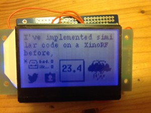
I’m trying to use a similar system at home for domestic purposes. Unfortunately, the setup of a Raspberry Pi in the kitchen (the place where I most often wonder what I’m just missing on the web, Twitter, eMail or, for that matter, the temperature) would be frowned upon. In my beyond-the-Raspberry Pi-phase, I had also explored the Arduino and mbed platforms, and with them the various ways how microcontrollers can control displays different from the widely known video standards. Now put a cheap SPI-controlled 128×64 pixel display (a ST7565 positive LCD with RGB backlight, e.g. from Phenoptix) for about £17 and a radio-controlled Arduino clone (the Ciseco XinoRF) together, and you realise that a wireless serial display for the Raspberry Pi is possible.
Now I don’t spend £30 on a XinoRF lightly (and to many RasWik users it is THE MOST IMPORTANT item of their kit). However, the RFµ-328 is a cost-efficient Arduino-compatible alternative that comes at about half the price. And here is where my troubles began. While I could easily wire my XinoRF to a level shifter and then to the display using a breadboard (see the ST7565 tutorial on the Adafruit Learning System), the first iteration of my RFu-based device featured some exciting soldering:
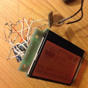
So what you see here is the two incoming wires of a 5V power supply, a 3V PowerPODÂ to control the incoming voltage, a RFu hidden behind the display and A LOT OF WIRES. Part of the problem is that the RFµ, the LCD, and the LCD backlight all require their own 3V/GND supply, and in this first iteration I had created power rails from solder blobs… …don’t try this at home.
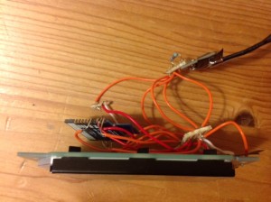
I’m no expert and my Google search “how to get away from breadboards and still be fire safe” guided me to stripboard. This was great in theory as it allowed me to replace the solder blobs with a more fundamental surface. However, the RFµ is designed towards surface mounting, and my SPI pins broke loose more often than not in this attempt:
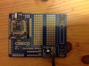
Just when I was about to give up on the idea of my wireless Raspberry Pi output, simply because I didn’t deem it safe to run when I’m not around, Ciseco launched the RFu Developer Board for a mere £4. This is the product I’d name a first born after them, if I had any left.
The Developer Board is just a circuit board with nothing on it. It’s bare. But it’s nicely designed in that it allows various power options (e.g. a battery, incoming DC cables, or power via a FTDI adapter). The battery and DC inputs run via a pad that has solder connections for a PowerPOD, and with that, applying up to 16V supports the RFu, 8 +/GND pairs (bottom of the board) , and a +/GND on an SPI-link (left on the board) with the appropriate 3V. The SPI pins of the RFu are broken out to this separate series of holes on the left of the board, and underneath and next to the RFu you have nice solder pads for more prototyping.
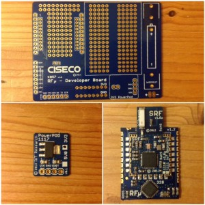
The entire build of my now final wireless display is shown in the next series of pictures. First, this is what you need on top of your SPI display and the external power supply: The dev board, the PowerPOD, and the RFu – just above £20 all together.
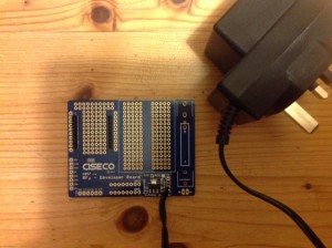
In the first step, I soldered on the PowerPOD to the dev board. There are four connections (Vin, GND, Vout, /) on the POD and at equivalent positions on the board. As my power supply had relatively solid cables, I used them to anchor the POD on the board, and I bridged the Vout between the POD and the board with some solid core wire. Following this step, I also soldered on the RFµ headers to the 2mm holes.
In Ciseco tradition there is very little documentation of the board available, but here I took the opportunity to check how the SPI pins are broken out to the left of the board. The relevant mapping for me was:
RFu pin 6 – MISO/SID (Arduino D12), pin 7 – MOSI/A0 (D11), pin 8 – SCK (D13), pin 9 - SS (D10), pin 11 – SCL (which I used for RST, A5).
At this stage, I also primed the RFµ for remote programming on the Explorer Plus. I’m going to write about the software underpinnings and the configuration of the wireless display at some other time. Today is just about the hardware.
With the RFu fitted.
In the final step, I then simply added a 220 Ohm resistor between the 3V support on the bottom to the breadboard, because the backlight prefers a wee bit of resistance and I’m going to take the voltage from the breadboard piece of the board. The Vdd and GND of the LCD I supplied from the SPI-bit on the left of the board, along with all the SPI data connections required.
The ultimate “product” from back, top and front is shown below. Now, I’m not afraid anymore to put this into a nice box and on the kitchen wall.
Note added about two year later: I’d be afraid again to put something like this into a nice box. Do a PCB. It isn’t that hard. :-)